

Contact Us
E-mail :
info@delinco.com, sales@delinco.com
WhatsApp:
+86-13930129172
Address:
271 Yuanshi Street, Shijiazhuang City, Hebei Province, China
.jpg")
DM(R) Series Slurry Pump
Suitable for medium to low lift industrial and mining applications in industries such as metallurgy, mining, coal, and power.
Capacity: 7~5000m³/h
Head: 5~59m
Speed (r/min): 1200~3800r/min
- Commodity name: DM(R) Series Slurry Pump
- Description
- Selection Chart
- Performance Parameter
- Installation Dimension
-
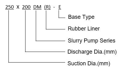
Model Meaning
Characteristic
Capacity: 7~5000m³/h Head: 5~59m Speed (r/min): 1200~3800r/min NPSHr(m) 2~4m Allowable Matting Max.Power(kW): 15~1200kw Material: M/RU Double pump housing structure. Efficient, wear-resistant, stable performance, and strong interchangeability of parts. The lining and impeller materials can be made of wear-resistant metal or rubber. The pump outlet direction can be rotated at 45 ° intervals for installation and use at eight different angles, and can be driven by belt or direct transmission. The shaft seal can use packing seal, auxiliary impeller seal, or mechanical seal. The rotation direction of the pump is clockwise when viewed from the drive end.
Application
Suitable for medium to low lift industrial and mining applications in industries such as metallurgy, mining, coal, and power, such as electric mining, metallurgy, power, steel mills, and chemical industry slurry transportation.
A hydraulic slurry pump is a robust and efficient pump used for transferring fluids containing solid particles such as slurries, sludge, or even highly viscous liquids. These pumps utilize hydraulic power to pressurize the system, providing high-pressure capabilities suitable for various industrial applications, including mining, construction, and waste management.
-
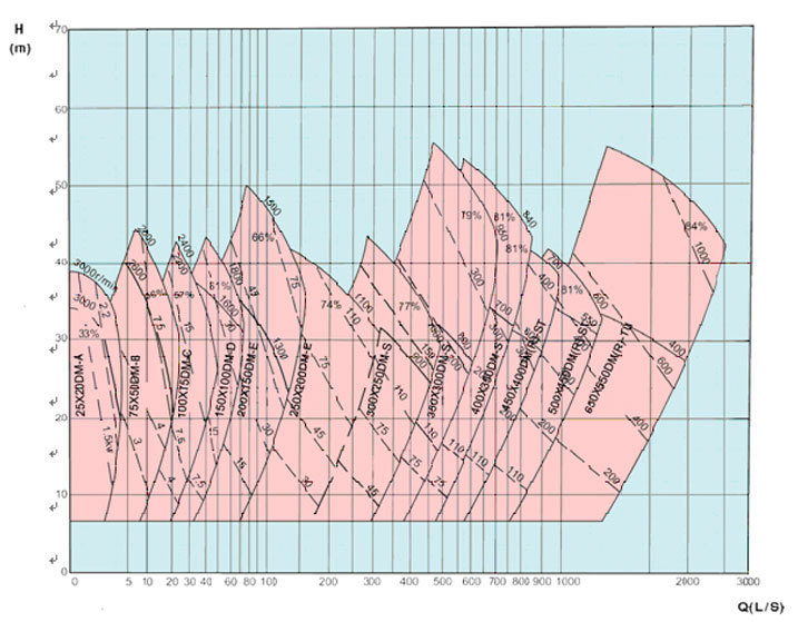
Section Chart of DM(R) Type Slurry Pump
-
Type Allowable Mating Max. Power(kW) Material Clear Water Performance Impeller Liner Impeller Capacity(Q) Head(H) Speed(n) Max. Eff. NPSH No. of Vanes Impeller Dia.(mm) (m³/h) (l/s) (m) (r/min) (%) (m) 25X20DM-A 7.5 M M 2.34~10.8 0.65~3 6~37 1400~3000 30 — 4 152.4 75X50DM-B 15 M M 16.2~76 4.5~20 9~44 1400~2800 55 — 4 190 100X75DM-C 30 M M 18~151 5~42 4~45 900~2400 57 — 4 229 150X100DM-D 60 M M 50~252 14~70 7~46 800~1800 60 2~3.5 4 305 200X150DM-E 120 M M 115~486 32~135 12~51.5 800~1500 65 2~6 4 381 250X200DM-E 120 M M 234~910 65~253 9.5~40 600~1100 64 3~6 4 457 300X250DM-S 120 M M 396~1425 110~396 8~30 500~800 77 2~10 5 550 350X300DM-S 560 M M 468~2538 130~705 8~60 400~950 79 2~10 5 653 400X350DM-S 560 M M 650~2800 180~780 10~59 400~840 81 3~10 5 735 450X400DM(R)-ST 560 M M 720~3312 200~920 7~51 300~700 80 2~10 5 825 M M 756~3312 210~920 7~37.5 6300~600 85 2~8 500X450DM(R)-ST 560 M M 1008~4356 280~1210 9~48 300~600 80 2~9 5 933 RU RU 1080~4356 300~1210 9~40 300~550 87 3~10 650X550DM(R)-TU 1200 M M 1980~7920 560~2200 10~50 250~475 86 4~10 5 1213 RU RU 1980~7920 700~2530 10~50 250~475 86 4~10 Note:1. M: wear-resistant alloy material, RU: rubber.
2. Capacity range recommend: 50%Q'≤Q~110%Q' (Q'≈ appropriate to capacity at highest efficiency point).
3. NPSH: appropriate to point Q recommend at highest speed. -
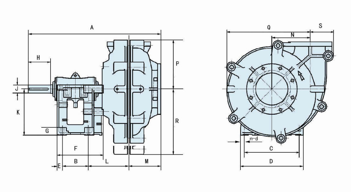
Model Outline Dimension A B C D E F G n-d H J K L M N 25X20DM-A 461 159 241 286 25 210 28 4-Ф18 57 20 145 89 90 86 75X50DM-B 642 143 254 295 24 248 38 4-Ф14 80 28 197 191 136 114 100X75DM-C 813 175 358 406 32 311 48 4-Ф19 120 42 254 253 163 146 150X100DM-D 950 213 432 492 38 364 64 4-Ф22 163 65 330 280 187 190 200X150DM-E 1218 257 546 622 54 448 76 4-Ф29 220 80 457 376 237 248 250X200DM-E 1334 257 546 622 54 448 76 4-Ф29 220 80 457 413 306 292 300X250DM-S 1406 490 560 680 50 590 70 4-Ф28 216 85 350 322 324 438 350X300DM-S 1720 640 760 920 70 780 90 4-Ф35 280 120 450 415 300 475 400X350DM-S 1776 640 760 920 70 780 90 4-Ф35 280 120 650 425 340 530 450X400DM(R)-ST 1840 620 900 1150 80 780 125 4-Ф48 280 120 650 480 375 600 500X450DM(R)-ST 1875 620 900 1150 80 780 125 4-Ф48 280 120 650 500 400 660 650X550DM(R)-TU 2400 860 1200 1460 95 1050 150 4-Ф79 350 150 900 625 500 860 Model Pump Head Size Inlet Flange Dimension Outlet Flange Dimension S Q R P O.D I.D C-C BET. Holes Holes O.D I.D C-C BET. Holes Holes 25X20DM-A 144 - - 128 114 25 83 4-Ф14 102 20 73 4-Ф14 75X50DM-B - 155 - 163 184 75 146 4-Ф19 165 50 127 4-Ф19 100X75DM-C 102 - - 204 229 100 191 4-Ф19 203 75 165 4-Ф19 150X100DM-D 118 - - 262 305 150 260 4-Ф22 229 100 191 4-Ф22 200X150DM-E 155 - - 324 368 200 324 4-Ф19 305 150 260 4-Ф19 250X200DM-E 199 - - 401 445 250 394 8-Ф22 382 200 337 8-Ф22 300X250DM-S 257 476 603 470 552 305 495 8-Ф32 483 254 425 8-Ф22 350X300DM-S 165 599 634 570 560 350 500 12-Ф26 530 300 470 12-Ф26 400X350DM-S 295 643 691 620 640 400 580 12-Ф26 590 350 530 12-Ф26 450X400DM(R)-ST 343 747 809 740 720 450 650 12-Ф33 685 400 615 12-Ф33 500X450DM(R)-ST 375 814 872 800 770 500 700 12-Ф33 740 450 670 12-Ф33 650X550DM(R)-TU 453 1055 1142 975 975 650 880 12-Ф39 900 350 800 12-Ф39
Keywords:
Slurry Pump
Get A Quote
Note: Please leave your email address, our professionals will contact you as soon as possible!
 Series FGD Pump")
 Series Slurry Pump")
 Series Slurry Pump")
 Series Slurry Pump")

Share

Copyright © 2022 Hebei Delin Machinery Co., Ltd.